2021年9月29日星期三

Launch X431 V+ PRO3: VCI Management Analysis & Activate Method

 Launch X431 V+ Pro3 auto diagnosis tablet Wifi 10.1inch Tablet Plus X431 HD3 Heavy Duty Module Support Both Cars and Trucks has Functions as Identification of control units, Adaptation of control units, Reset service intervals, Reading vehicle data streams, Display of current system parameters, Check actuators, Reading and erasing vehicle fault codes.

launch-x431-v+-pro3-vci-management-analysis-activate-method-1

Launch X431 V+ PRO3 auto programmer VCI option allows you to manage all your activated VCI devices.

If several VCI devices are activated on this tool, a list of VCIs will be displayed on the screen. Once you choose the VCI that belongs to other account, you have to log out, and then input the right account to continue.


There are twos kinds of VCI Management methods, check for details:

(1)VCI Management (Only for Passenger Vehicle Configuration)

This option is used for the tablet to deactivate pairing up with the VCI device via Bluetooth.


(2)VCI Management (Only for Commercial Vehicle/Gasoline & Diesel Configuration)

This option is used to set the communication method between the tablet and the VCI module.

launch-x431-v+-pro3-vci-management-analysis-activate-method-2


To ensure the tablet can work with the VCI module via Wi-Fi communication, please follow the steps below to proceed:

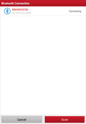
  1. Check the box “Use Wi-Fi communication mode”, the system will search for VCI module automatically.

launch-x431-v+-pro3-vci-management-analysis-activate-method-3 launch-x431-v+-pro3-vci-management-analysis-activate-method-4


  1. Tap the desired VCI module and a pairing request similar to the following prompt window will appear:

launch-x431-v+-pro3-vci-management-analysis-activate-method-5


  1. Tap “PAIR” to start pairing. Once the pairing is successfully done, the screen displays:

launch-x431-v+-pro3-vci-management-analysis-activate-method-6


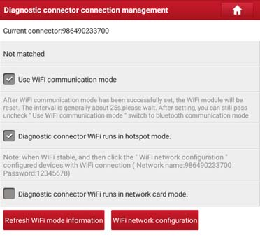
  1. There are two Wi-Fi communication modes available for the VCI module.
  • Work as Wi-Fi hotspot: Once enabled, the VCI module and the tablet automatically connect and form a LAN network to make communication. In this case, the tablet cannot surf the Internet.
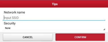
  • Work as network adaptor: Once enabled, a Wi-Fi connection dialog box appears:

launch-x431-v+-pro3-vci-management-analysis-activate-method-7


Input the Wi-Fi network name and access password (if the network is encrypted) until it is properly connected. In this case, the tablet can surf the Internet and communicate with the VCI module.

Important message: please be sure to keep the VCI powered on while performing the operation.


But here comes the question? How to activate VCI?

The VCI activation method is shown as below:

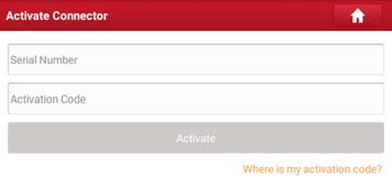
This item lets you to activate a new VCI device.

launch-x431-v+-pro3-vci-management-analysis-activate-method-8


Input the Serial Number and Activation Code, and then tap “Activate” to activate the connector. For details on how to obtain Activation Code, tap the link below to get help.


That's all. Thank you for sharing your time with us!

Don't forget to contact us at:

Email:  sales@CarDiagTool.co.uk
Skype: cardiag.co.uk
Whatsapp: +86 15002705698

Or leave a message at https://www.cardiagtool.co.uk/

to tell us what suggestions or questions you have about our products.

Source:http://blog.cardiagtool.co.uk/launch-x431-v-pro3-vci-management-analysis-activate-method/

2021年9月28日星期二

Xhorse VVDI2 Immobilizer Key Tool Transponder Programming Tutorials

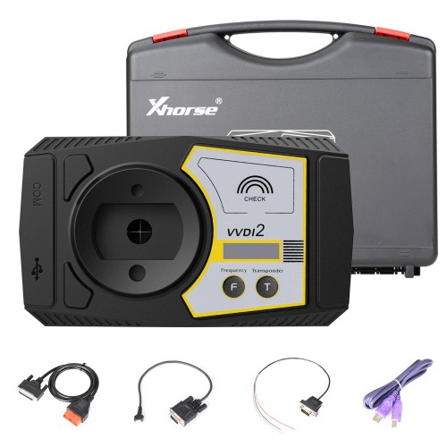
 As a multifunctional automotive diagnostic platform designed for automotive maintenance, Xhorse VVDI2 Immobilizer Key Programmer supports the following functions:

(a)For Volkswagen Software:
Support for Volkswagen, for Audi, for Skoda, for Seat, for Porsche, for Bentley  ect.
Main Function:Diagnose,4th immo,5th immo system
Learn key
remote adaptation
change KM
Program Engine control unit(Passat ICC By OBD)
Unlock Immo1/Immo2 firmware protection
Support data manipulation tools
K-line instrument /immo box
adapt unit module component protection, dump tool and so on

(b)For Porsche Software:
Support file make key and key learn by OBD2
EEPROM support:1L15Y,2M25J,5M48H,1N35H

xhorse-vvdi2-immobilizer-key-tool-transponder-programming-tutorial-1


When use Xhorse VVDI2 professional tool to perform Transponder Programming function, customers should know the knowledge and use tips below.

It can Support the following types:

1) Autodetect Transponder

2) PCF7930/PCF7931/PCF7935

3) HITAG2

4) HITAG2+ EE

5) HITAG2 Extended

6) HITAG3

7) HITAG Pro

8) HITAG (BMW)

9) HITAG (VAG)

10) MEGAMOS13

11) MEGAMOS48

12) MEGAMOS8E

13) TEMIC 11/TEMIC 12

14) TEMIC 8C

15) TIRIS 4C

16) TIRIS DST 4D/4E

17) TIRIS DST+

18) T5/TK5551


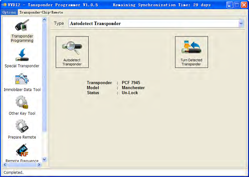
(1)How can it auto-detect other transponder devices?

Input transponder to VVDI2 programmer, press button “Auto-detect Transponder”, it will detect transponder type and simple status information. You can turn to specify type after success read. Auto-detect Transponder function can run without software, just provide power to VVDI2, press button “T” on the device, transponder type will show in the LCD display

xhorse-vvdi2-immobilizer-key-tool-transponder-programming-tutorial-2


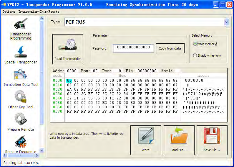
(2)PCF7930/PCF7931/PCF7935

Many old cars use this transponder as immo transponder, this transponder support generate many types special transponder. It mainly contains Password, Main memory, Shadow memory etc. Note: PCF7930 and PCF7931dont have Shadow memory, only have Main memory. PCF7935 have this 2 memory both. Shadow memory only has 16 bytes

Write: You need read transponder success before write, modify the position to your expect value, the byte will change read after edit, then write to transponder.

xhorse-vvdi2-immobilizer-key-tool-transponder-programming-tutorial-3


Read Transponder: Read Main memory don’t require password

Write: For the transponder enabled Password feature, you must place correct password in Password area before write


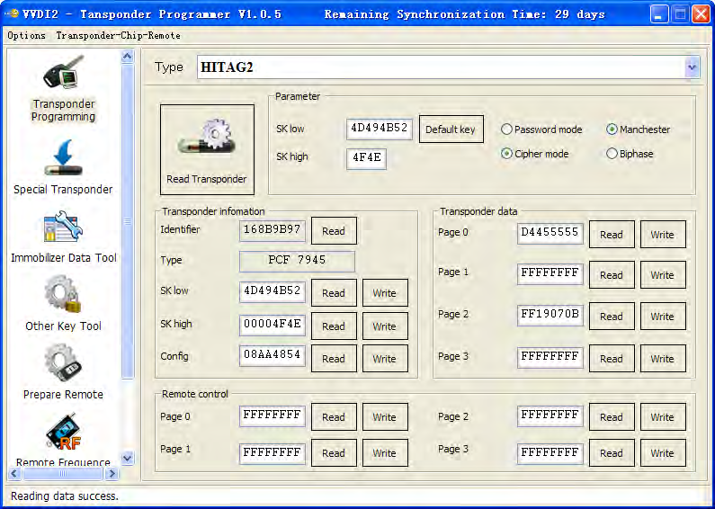
(3)HITAG2

HITAG2 is very popular immo transponder, t is compatible with PHILIPS

PCF7936 transponders. It support following types:

PCF7936

PCF7941

PCF7942/44

PCF7943

PCF7945

PCF7946

PCF7947

PCF7952

PCF7953

PCF7961

(There’s some other HITAG2 transponder made by small company, it don’t have the above type, but also support)

Access method shown as below

PCF7936 support Password mode and Cipher mode

Other’s don’t have Password mode itself, only have Cipher mode

For Password mode: Only SK low was used for login,Default key:4D494B52

For Cipher mode: It use SK low and SK high for login, Default key: SK low:

4D494B52; SK high: 4F4E

Coding method shown as below :

Support Manchester and Biphase coding (Note: Most immo transponder use

Manchester coding, rarely use Biphase type)

xhorse-vvdi2-immobilizer-key-tool-transponder-programming-tutorial-4


How to Read Transponder?

  1. It will read all readable page and shown in window (Transponder information,Transponder data, Remote control(not all transponder have this area)),it will try password mode and cipher mode automatically, also Manchester and Biphase automatically. For the transponder with default key we can read all readable pages. If the transponder was changed SK value, we can only read ID before you input correct SK value in Parameter. Every page in HITAG2 has 4 bytes. The type is detect with identifier, so it will not strictly for many OEM keys
  2. About the transponder manufacture configuration(TMCF)

TMCF byte is very important; usually it is the first byte in Config page. Example: Config page is “XXYYZZWW” (4 bytes). The first byte “XX” is TMCF,write error TMCF value can lock the transponder or damage it. The specify explanation for TMC following: Convert XX(hex) to binary, it have 8 bits, every bit can be 0 or 1, we set as: X1 X2 X3 X4 X5 X6 X7 X8

Whats the meanings of X1 X2 X3 X4 X5 X6 X7 X8 ?

X1: If set to 1, the SK low and SK high was unable to read and write

X2: If set to 1, the Config page was unable to write, but read is always available

X3: If set to 1, Remote control area was unable to read and write(Note: PCF7936

have none about this bit)

X4: If set to 1, transponder data was unable to write, but read is always available

X5: If set to 1, transponder is use transponder data area. If set to 0, mean use remote control area (Attention: For PCF7936, if set to 1, transponder use Cipher mode, if set to 1, transponder use Password mode)

X6: Always 0, reserve bit (Attention: PCF7936 must set to 1, set to 0 will damage transponder)

X7: Always 0, reserve bit (Attention: PCF7936 must set to 1, set to 0 will damage transponder)

X8: If set to 0, transponder use Manchester coding, if set to 1, use Biphase coding (CDP)


How to change a byte to binary: With PC system Calculator ->Select Scientific->Select Hex ->input TMCF value ->Select Bin, you can see the binary values. If binary not havetotal 8 bits, means the front have several 0

Example: TMCF value is C8, so X1-X8 have value: 11001000

The transponder use Manchester coding

The transponder use transponder data area

The SK low and SK high was unable to read and write

The Config page was unable to write, but support read

That's how it goes with Xhorse VVDI2 Immobilizer Key Tool to perform transponder programming. You guys would learn quite a lot.


Don't forget to contact us at:

Email:  sales@CarDiagTool.co.uk
Skype: cardiag.co.uk
Whatsapp: +86 15002705698

Or leave a message at https://www.cardiagtool.co.uk/

to tell us what suggestions or questions you have about our products.

Source:http://blog.cardiagtool.co.uk/xhorse-vvdi2-immobilizer-key-tool-transponder-programming-tutorials/
Xhorse VVDI Prog: Software Overview, Driver Installation & Software Update

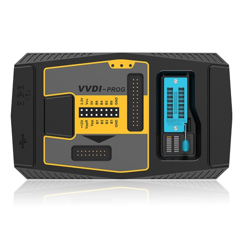
 Xhorse VVDI PROG Auto Programmer has Highlights that gain attention from customers worldwide that are shown as below:

  1. Built-in update software: Make VVDI Prog firmware update timely.
    Latest Software Version: V5.0.6, Firmware Version: 2.0.0
  2. High-speed USB communication interface: Make software automatically connect.
  3. Smart operation mode: possible causes of error will be listed
  4. Reserve ports: For future update.
  5. Self-test function: Check if the machine works well or not.
  6. Power supply: Through USB cable, software will automatically prompt if the external USB power supply is needed
  7.  Multi-language: English, French, Italian, Polish, Portuguese, Spanish, Turkish, Czech, Russian, Arabic
  8. Get free BMW ISN read function and NEC, MPC, Infineon etc chip continously update service

xhorse-vvdi-prog-software-overvbiew-driver-installation-software-update-1

This article has three parts of contents for customers reference when using Xhorse VVDI Prog auto programmer.

That mainly covers its Software Overview, Driver Installation & Software Update.


Part 1.Software Overview

Firstly for its Introduction

(1)Support R&W lots of chips, include MC9S08 series, MC68HC(9)12series, MC9S12series,V850series, H8Xseries, R8Cseries, PCF79XXseries and most eeprom chips etc .

(2)Support chip data verify, checkblank function

(3)Support data file compare function

(4)Support R&W BMW N20, N55 ECU(show ISN directly)

(5)Stable R&W MC9S12XE series chips(5M48H/1N35H/2M53J/3M25J etc.)

(6)Support renew PCF79XX remote, currently support BMW E/F series

(7)Lots of connection diagram

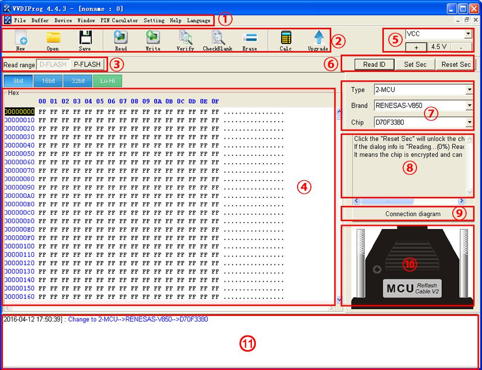
Secondly for its Software interface

xhorse-vvdi-prog-software-overvbiew-driver-installation-software-update-2


Below shares for their explanation.

  1. Operation options

File : Load data file

Buffer : Support copy, paste, search, fill function

Device : Support chip read, write, erase operation

Window : Compare two data files

Setting : Read&Verify, Write&Verify, Erase&Check Blank configuration

Language : Change the language, current support English, Chinese,

Polish, Arabic, Czech, Spanish, French, Italian, Portuguese, Russian,

Turkish

  1. General options

Provide General function buttons, simple and easy for operation, include:

new, open, save, read, write, verify, check blank,erase,calculator &

upgrade

  1. Read range

Parts of chips include several data areas, for example EEPROM, FLASH

and etc. click on the button select read range

  1. Data display

Display the read data or load data, include hex and ASCII format

  1. Power configuration

Display the status of power ( VCC, VPP, 12V), support change the voltage

of VCC and VPP (The default voltage usually not need to change)

  1. Special function options

Provide chips special function, for example parts of chips have read chip

ID, set security, reset security etc .

  1. Chip option

Select right option according to type,brand and chip

  1. Option Information

Display parameter information of current option

  1. Connection diagram button

Click on button, get the connection diagram of current chip

  1. adapter Type

Display needed adapter of current option

  1. Operation Information

Display operation information and saved in “log.bin” file


Part 2.Driver Installation

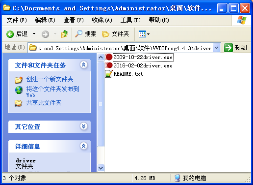
The driver install software saved in “driver” folder, include 2009 and 2016 version (recommend select 2009 version)

xhorse-vvdi-prog-software-overvbiew-driver-installation-software-update-3


Part 3.Software Update

This function require internet support

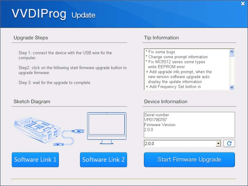
Click the “Upgrade” button enter the upgrade interface, show as following picture

xhorse-vvdi-prog-software-overvbiew-driver-installation-software-update-4


(1)Enter update interface,if software show”communication with server failed”,please close your Anti-virus and computer firewall and retry.

If software show“unable to find equipment”,please reconnect device

(2)Tip information show the latest software version and upgrade information

(3)Device information show the device SN, device firmware version and the latest firmware version

(4)Firmware upgrade steps:

  1. Select the firmware version
  2. Click “Start Firmware Upgrade” button
  3. Don’t close or pull out USB cable before upgrade finished

(5)Software upgrade steps:

  1. Click “Software Link 1” or “Software Link 2” button, download software

from the web

  1. Extract the file


That's all. Thank you for sharing your time with us!

Don't forget to contact us at:

Email:  sales@CarDiagTool.co.uk
Skype: cardiag.co.uk
Whatsapp: +86 15002705698

Or leave a message at https://www.cardiagtool.co.uk/

to tell us what suggestions or questions you have about our products.

Source:http://blog.cardiagtool.co.uk/xhorse-vvdi-prog-software-overview-driver-installation-software-update/

2021年9月26日星期日

How to Make a Working Key with Xhorse VVDI2 Transponder Immobilizer Tool?

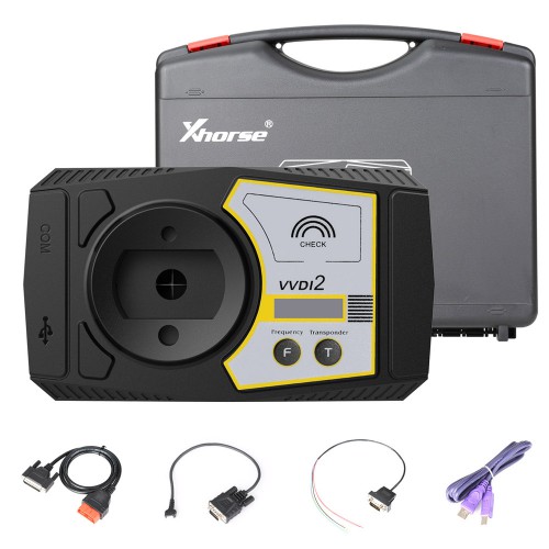
Xhorse VVDI2 Transponder Key Programmer is Full Authorized functional tool, a multifunctional automotive diagnostic platform designed for automotive maintenance such as key programming, module programming, diagnostics and more by VVDI.

how-to-make-a-working-key-with-xhorse-vvdi2-key-tool-1


It has the following advantages that makes it appeal to customers:

1.Free Lifetime Online firmware and software update
2.Free active MED17/EDC17 PIN / CS / MAC authorization and English remote database.

3.The VVDI 2 has all VVDI functions,Improved and more stable, more vehicle coverage, multi-immo functions.
4.Xhorse VVDI2 has the function of Tango key programmer, remote control generation and chip identification is improved also the antenna stabilitly had enhanced. More over,
users don't need to connect VVDI2 Programmer with computer or other device to identify chip or detect remote frequency.
5. Add more vehicle models.The old VVDI programming device support diagnostic function only for VAG groups, but VVDI2 had achieved multi-brand vehicle diagnostic and support parts of vehicle immo programming function,VAG key programmer and much other brands.
6. VVDI2 tool can replace lots of customized devices.


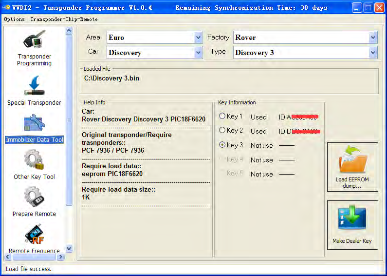
Xhorse VVDI2 Immobilizer Data Tool can load car immobox EEPROM dump, make a working key directly. Provide detail transponder type and EEPROM type accord selected car: car original transponder, require new transponders, EEPROM chip,EEPROM size etc


How to make a working key with immobox EEPROM dump file, steps are shown as follows:

Step 1:Load immobox EEPROM dump (BIN file) with Load EEPROM dump…, it will display

used key ID, key number, and PIN(if it have) etc

Step 2: Select a key position for new key

Step 3: Input a blank key to VVDI2 programmer, Press button Make Dealer Key

Step 4: After make key success, if you get save new EEPROM window, you need write new dump file to immobox to make new key working(Expect there’s special note). If there’s no save new EEPROM window, the made key can start engine directly

how-to-make-a-working-key-with-xhorse-vvdi2-key-tool-2


Additional share for customers:

Xhorse VVDI2 Use Tips:

You’d better use VVDI Programmer for read Immobox EEPROM dump file

(1)When you save new EEPROM dump, DON’T write to original dump file, save a new

name

(2)For VAG CDC32xx type, some type need FLASH for make dealer key

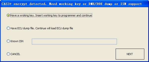
(3)For BMW CAS3+ encrypt version, we need working key, engine EEPROM dump or

ISN support 

(4)For some special immobox, VVDI2 can fix the crashed EEPROM dump to new one.

Please load new saved EEPROM dump and make key

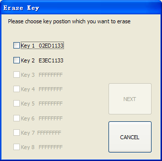
(5)Porsche support Erase key, after ease key will save new dump. Make dealer key

should load new dump 

how-to-make-a-working-key-with-xhorse-vvdi2-key-tool-3 how-to-make-a-working-key-with-xhorse-vvdi2-key-tool-4

That's how it goes with Xhorse VVDI2 Auto Immobilizer Tool in making a working key.


That's all. Thank you for sharing your time with us!

Don't forget to contact us at:

Email:  sales@CarDiagTool.co.uk
Skype: cardiag.co.uk
Whatsapp: +86 15002705698

Or leave a message at https://www.cardiagtool.co.uk/

to tell us what suggestions or questions you have about our products.

Source:http://blog.cardiagtool.co.uk/how-to-make-a-working-key-with-xhorse-vvdi2-transponder-immobilizer-tool/

2021年9月24日星期五

MB SD C4 C5 Diagnostic Tools Hardware Upgrade Instructions

 MB Star Diagnostic Tools have two versions like 2020.03 MB SD C4 and V2021.6 MB SD C5 now for their Hardware Upgrade Instructions.

MB SD Connect Compact 5 diagnostic tool has same function as SD C4 but with new design, support both cars and trucks, support wireless connection.

mb-sd-c4-c5-diagnostic-tools-hardware-upgrade-instructions-1

While 2020.03 MB SD C4 diagnostic tool is still great Connect Compact 4 For Mercedes Benz Diagnosis WIFI Version, both compatible on WIN7 and WIN10.

mb-sd-c4-c5-diagnostic-tools-hardware-upgrade-instructions-2


For their hardware upgrade, there are two paths available:

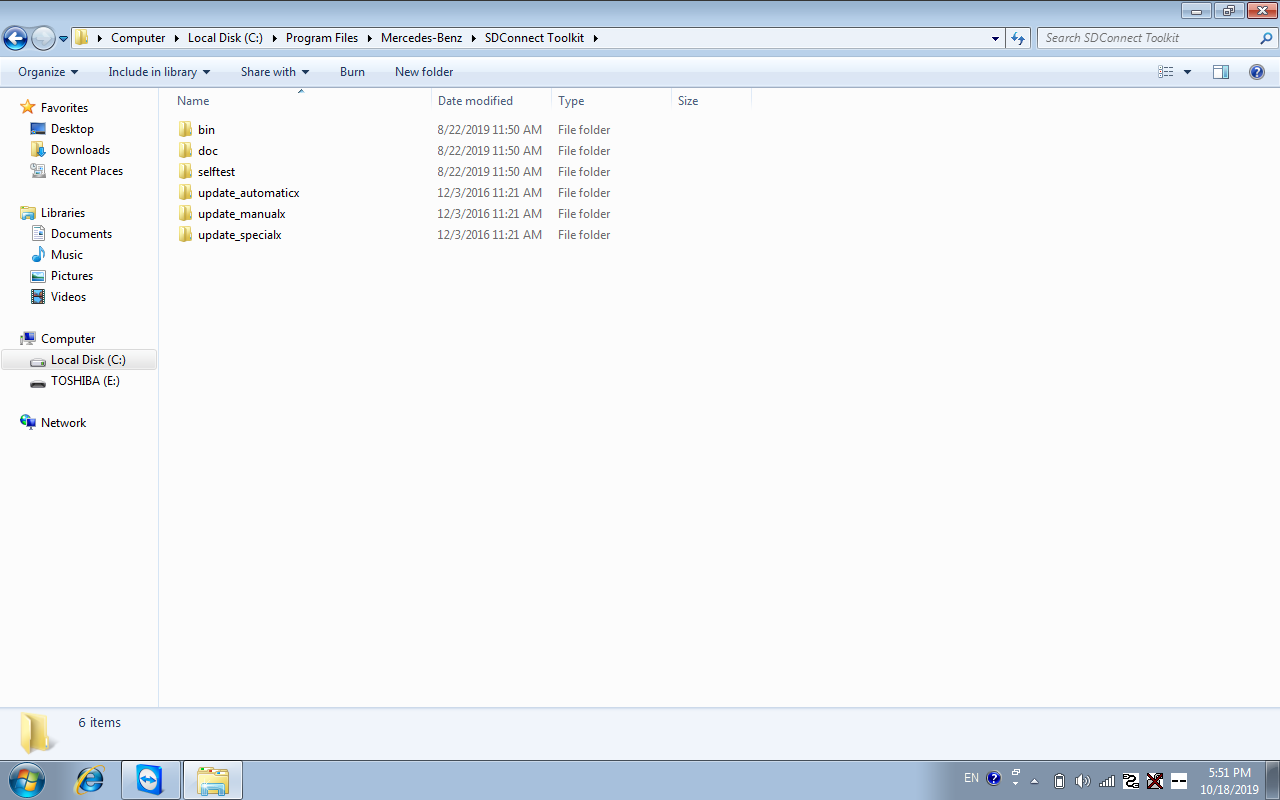
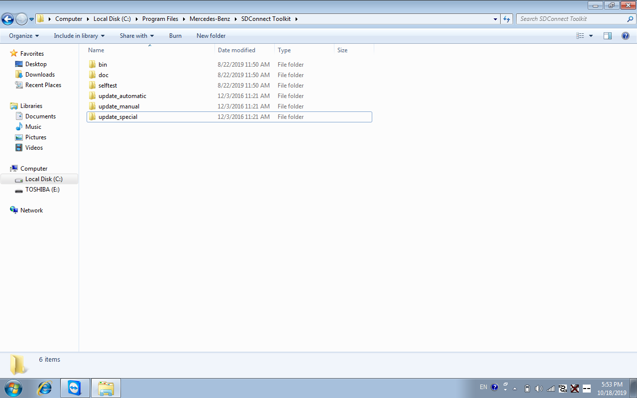
(1)Path one:C:\Program Files\Mercedes-Benz\SDConnect Toolkit

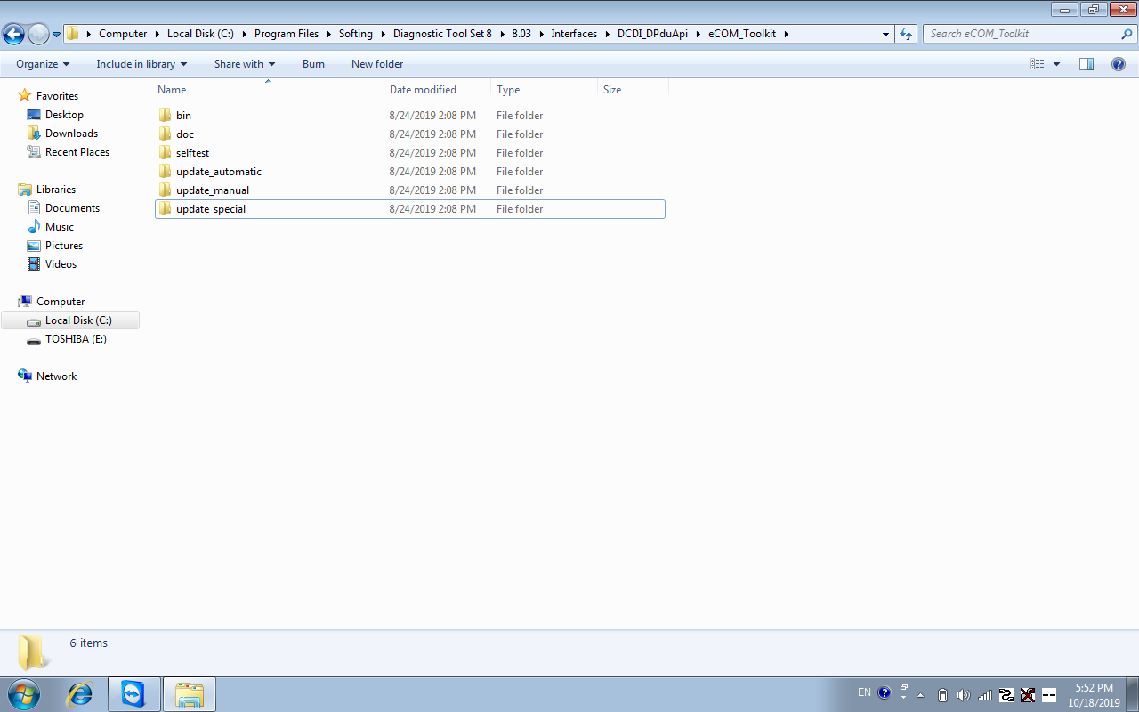
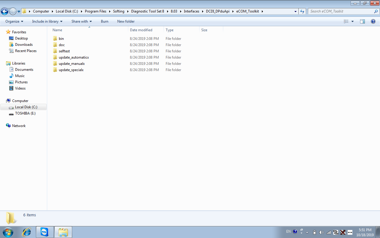
(2)Path two:C:\Program Files\Softing\Diagnostic Tool Set 8\8.03\Interfaces\DCDI_DPduApi\eCOM_Toolkit

  • Change the three file names of update_automaticx, update_manualx, and update_specicalx under path one and path two to update_automatic, update_manual, and update_specical (remove the letter x at the end of the file name). After the modification, see Figures 3 and 4 below.
  • After changing the file name, the computer restarts
  • C4 and C5 need to install 6 AA batteries (see steps 1 pdf for details) [sp100-e doip hardware upgrades do not need to install batteries]
  • Obd main line should be connected to car or 12v power supply

mb-sd-c4-c5-diagnostic-tools-hardware-upgrade-instructions-3 mb-sd-c4-c5-diagnostic-tools-hardware-upgrade-instructions-6 mb-sd-c4-c5-diagnostic-tools-hardware-upgrade-instructions-5 mb-sd-c4-c5-diagnostic-tools-hardware-upgrade-instructions-4

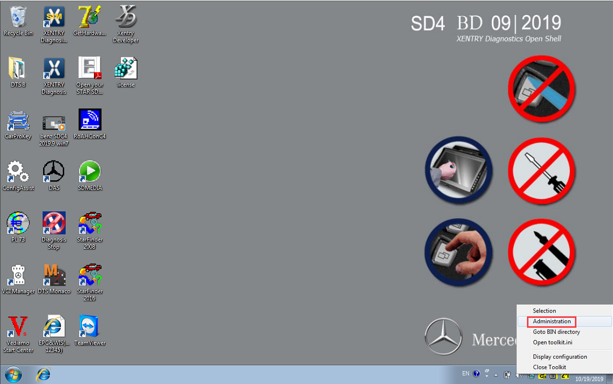
 Right-click on the lower right corner of the computer to select administration, and then select Software update

mb-sd-c4-c5-diagnostic-tools-hardware-upgrade-instructions-7

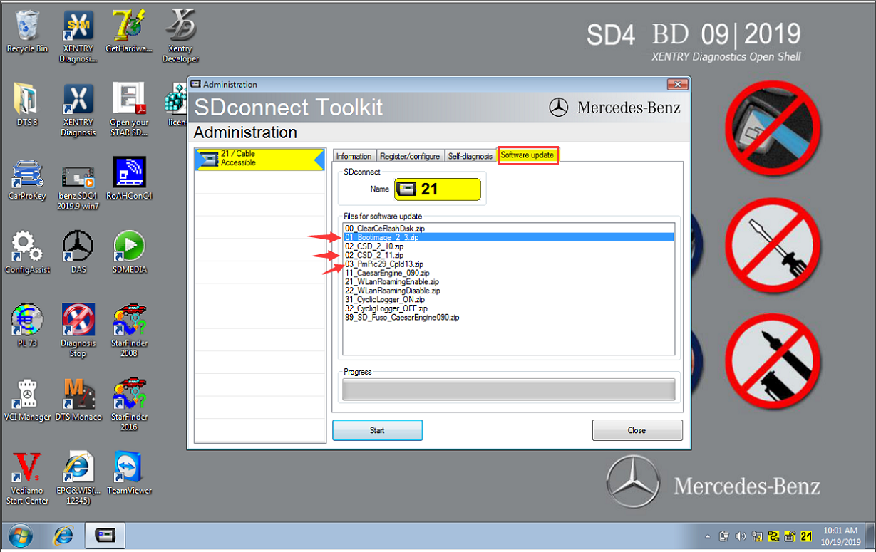
Mainly upgrade three files, as shown in the figure below, the upgrade sequence is 00——>02——》01——》03

mb-sd-c4-c5-diagnostic-tools-hardware-upgrade-instructions-8

As long as you follow the above upgrade instructions accordingly step by step, no problem would occur for your tool’s hardware. Wait for big success!


That's all. Thank you for sharing your time with us!

Don't forget to contact us at:

Email:  sales@CarDiagTool.co.uk
Skype: cardiag.co.uk
Whatsapp: +86 15002705698

Or leave a message at https://www.cardiagtool.co.uk/

to tell us what suggestions or questions you have about our products.

Source:http://blog.cardiagtool.co.uk/mb-sd-c4-c5-diagnostic-tools-hardware-upgrade-instructions/
2021年9月22日星期三

Launch X431 V+ PRO3 Tutorial: How to Perform Remote Diagnose?

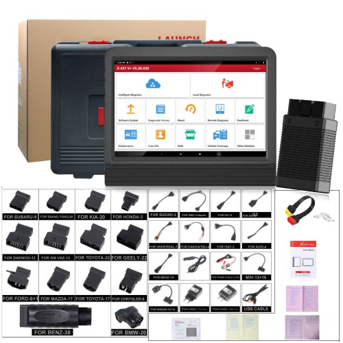
 Launch X431 V+ Pro3 Professional Auto Diagnostics Wifi 10.1 inch Tablet Plus X431 HD3 Heavy Duty Module Support Both Cars and Trucks.

launch-x431-pro3-tutorial-how-to-perform-remote-diagnosis-1


This tool has the option of “Remote Diagnose” aims to help repair shops or technicians launch instant messaging and remote diagnosis, making the repair job getting fixed faster.

Tap “Remote Diagnose” on the Job menu, the screen appears blank by default.


Part 1.CHECK Launch X431 V+ PRO3 App’s Interface Layout:

launch-x431-pro3-tutorial-how-to-perform-remote-diagnosis-2


1Home buttonTap it to navigate to the Job menu screen.
2Search bar

Directly input the registered username of the tool to start

searching, and then tap the desired one to add it into your

friend list.

3

Friend list

display area

By default it appears blank.
4Message tab

Once an incoming message reaches, a red dot will appear

on the upper right corner of the tab.

5Contact tabTap to enter the friend list.
6

Remote

switch

Tap to slide the switch to ON, the tool keeps online and

becomes accessible on the web client. In this case, inform

the technician of your product S/N, and he/she will control

your device remotely.


Part 2.How to Add Friends?

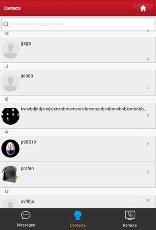
Tap “Contact” to enter the contact page. By default it appears blank.

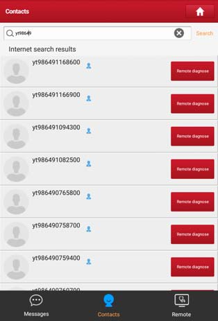
In the search bar, input the partner’s username and tap “Search” button next to  the search bar to starts searching from Launch’s golo business database.

The partner must be the users who have registered their Launch’s diagnostic tools. They may be the following:

  • Workshop
  • Technician
  • golo users

Once the result matches the keyword, a screen similar to the following will appear:

Here you can tap “Remote Diagnose” to launch remote diagnostics directly or choose to add the partner into the Contacts list.

launch-x431-pro3-tutorial-how-to-perform-remote-diagnosis-3


Tap the desired name from the list, the following screen appears:

launch-x431-pro3-tutorial-how-to-perform-remote-diagnosis-4


Tap “Add friend”, a dialog box pops up:

launch-x431-pro3-tutorial-how-to-perform-remote-diagnosis-5


Tap “CONFIRM” to send your request.

Once the partner receives the request, a beep will sound. Tap the “Message” tab:

  • Once the partner agreed your request, he/she will automatically be listed in the Contact tab.
  • If a technician sent you a friend request, you can tap “Agree”to confirm and his/her name will appear in the friend list (Contact). Or tap “Ignore”to ignore this request.

launch-x431-pro3-tutorial-how-to-perform-remote-diagnosis-6


Part 3.How to Start Instant Messaging?

Please have your attention here: The I/M (Instant Messaging) function is open to all users who had Launch’s diagnostic tool equipped with this module.

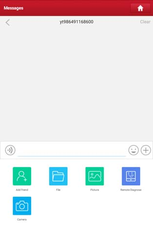
After adding your friends, tap the desired one’s photo to enter a screen similar to the following:

launch-x431-pro3-tutorial-how-to-perform-remote-diagnosis-7


Tap the input field and use the on-screen keyboard to enter the text message,

and then tap “Send” to send it.

Tap  to send the voice message.

Tap  to send the emoj.

Tap  to call out more function options.

launch-x431-pro3-tutorial-how-to-perform-remote-diagnosis-8


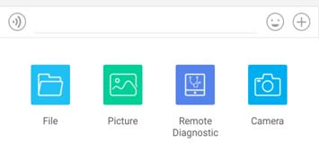
File: Choose diagnostic reports or local files to send.

Picture: Choose screenshots or pictures to send.

Remote Diagnostic: To start a remote diagnostic session.

Camera: Open camera to take pictures.

Tap “Clear” to delete all the partner’s dialog logs.

Tap “Close” to close the current dialog.


Part 4.How to Perform Launch Remote Diagnosis (Device-To-Device)?

The tool is allowed to initiate remote diagnosis with other diagnostic tools

(including but not limited to the X-431 PRO3 V4.0) of Launch family, which are

equipped with this module.

Please have your attention here: Before performing this operation, please make sure the following no matter which side sends the remote request:

  • Turn on the vehicle power supply.
  • Throttle should be in a closed position.
  • The tool should be properly connected to the vehicle’s DLC and a successful communication is required.

On the function option selection screen, tap “Remote Diagnostic”, a pull-down

menu including the following options appears:

launch-x431-pro3-tutorial-how-to-perform-remote-diagnosis-9


These options are defined as follows:

ActionsResults

Request control

remote device

Request to control the partner’s device remotely to help him diagnose the vehicle.

*Notes:

·Remote diagnosis has the same diagnostic steps as

manual diagnosis.

·In process of remote diagnosis, tap the button to send a voice message.

·Once vehicle diagnosis is complete, a report will be

created. Input your comments on this report, and then

tap “Send Report” to send it to the partner.

Invite remote

diagnostic assistant

If you need support, just use this option to invite a

technician to perform a remote control on your tool.

*Notes:

·Remote diagnosis has the same diagnostic steps as manual diagnosis.

·In process of remote diagnosis, tap the button to send voice message.

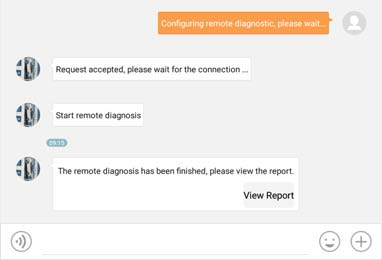
·Once you received the report from the partner, tap “View Report” to view details. All diagnostic reports are saved under the “Remote Reports” tab of “My

Reports” in “User Info”.

launch-x431-pro3-tutorial-how-to-perform-remote-diagnosis-10

CancelTo cancel this operation.


Part 5.How to Perform Launch Remote Diagnosis (Device-To-PC)?

Except that the remote diagnosis can be done between different Launch’s diagnostic tools that come loaded with the module, user also can ask for remote control from PC client technician.

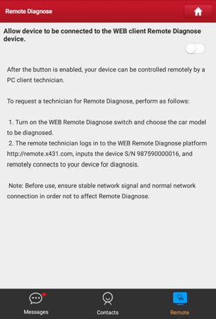
Tap the “Web Remote” tab, the screen displays as follows:

launch-x431-pro3-tutorial-how-to-perform-remote-diagnosis-11


  1. Slide the switch “Allow device to be connected to the WEB client remote

diagnostic device” to ON so that the partner can find and connect to this

device while using the PC.

  1. Notify the partner of the PC client website http://remote.x431.com. When the

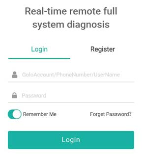
partner accesses the link, the PC displays as below:

launch-x431-pro3-tutorial-how-to-perform-remote-diagnosis-12


  1. Tell the partner to input his own official technician account and password, and then tap “Login”to navigate to the following figure.

launch-x431-pro3-tutorial-how-to-perform-remote-diagnosis-13


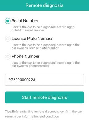
  1. Tell the partner to check the box “Serial number”and enter the Serial Number provided by you, and then tap “Start remote diagnosis”to control your device remotely.


In process of remote diagnosis, please note the following things:

1) You are not suggested to execute any actions.

2) The partner is not allowed to save any diagnostic reports or records on your handset.

The operations in remote diagnosis are same as those in local diagnose. Once the session is complete, a remote diagnostic report will be automatically generated.

That's all about the Launch X431 V+ Pro3 Professional Auto Diagnostics performing remote diagnose special function.


That's all. Thank you for sharing your time with us!

Don't forget to contact us at:

Email:  sales@CarDiagTool.co.uk
Skype: cardiag.co.uk
Whatsapp: +86 15002705698

Or leave a message at https://www.cardiagtool.co.uk/
to tell us what suggestions or questions you have about our products.

Source:http://blog.cardiagtool.co.uk/launch-x431-v-pro3-tutorial-how-to-perform-remote-diagnose/

2021年9月18日星期六

How to Prepare Your Launch X431 V+ PRO3 to Be Ready For Vehicle Test?

 Launch X431 V+ Pro3 Auto diagnostic scanner Wifi 10.1inch Tablet Plus X431 HD3 Heavy Duty Module Supports Both Cars and Trucks for diagnostics. It is 2 years free update online, and X431 HD3 Heavy Duty Module is with one year free update. They can still work well without update.

how-to-prepare-your-launch-x431v+-pro3-ready-for-vehicle-test-1


This article aims to tell the customers “How to Prepare Your Launch X431 V+ PRO3 to Be Ready For Vehicle Test”. Check specific content below.


We should first know the Diagnostics toolbar of this tool:

The diagnostics toolbar contains a number of buttons that allow you to print the displayed data or make other controls. It is displayed on the upper right corner of the screen and goes through the whole diagnostic session. The table below provides a brief description for the operations of the diagnostics toolbar buttons:

NameButtonDescription
Home1Returns to Job menu screen.
Print2

Tap to print the current screen. To perform

printing, you need to purchase an extra Wi-Fi

printer manufactured by LAUNCH separately

and then properly configure the wireless printer

Exit3To exit the diagnostic application.

After that, we should also know how to do the “Connections” in this tool.

Supposing it is under Normal testing conditions:

  • Turn on the vehicle power supply.
  • Vehicle battery voltage range should be 9-18V.
  • Throttle should be closed at its close position.


Get to know the DLC location:

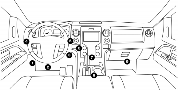
The DLC (Data Link Connector or Diagnostic Link Connector) is typically a standard 16-pin connector where diagnostic code readers interface with the vehicle’s on-board computer. The DLC is usually located 12 inches from the center of the instrument panel (dash), under or around the driver’s side for most vehicles. If DLC is not located under dashboard, a label should be there telling location. For some Asian and European vehicles, the DLC is located behind the ashtray and the ashtray must be removed to access the connector. If the DLC cannot be found, refer to the vehicle’s service manual for the location.

how-to-prepare-your-launch-x431v+-pro3-ready-for-vehicle-test-2

Then, (1)the Vehicle connection (For Passenger Vehicle Configuration):

The method used to connect the VCI device to a vehicle’s DLC depends on the vehicle’s configuration as follows:

  • A vehicle equipped with an OBD II management system supplies bothcommunication and 12V power through a standardized DLC.
  • A vehicle not equipped with an OBD II management system suppliescommunication through a DLC connection, and in some cases supplies 12Vpower through the cigarette lighter receptacle or a connection to the vehicle battery.

Follow the steps mentioned below to connect OBD II vehicle:

  1. Locate vehicle’s DLC socket.
  2. Plug the VCI device into the vehicle’s DLC socket (It is suggested to use theOBD II extension cable to connect the VCI device and DLC socket).
  3. Choose one of the two ways to obtain power from:
  4. Power adaptor: Connect one end of the included power adaptor tocharging port of the tablet, and the other end to AC outlet.
  5. Internal battery pack


For non-OBDII vehicle, proceed as follows:

  1. Locate vehicle’s DLC socket.
  2. Select the corresponding non-16pin connector.
  3. Plug the non-16pin end of the connector into the DLC socket, then connecttheother end to the OBD I adaptor, and then tighten the captive screws.
  4. Connect the other end of the adaptor to the included VCI device.
  5. If the pin of the DLC is damaged or has insufficient power, please follow theeither of the following methods to proceed:

A.Cigarette Lighter cable (optional): Connect one end of the cigarette lighter cable to vehicle’s cigarette lighter receptacle, and the other end to the power jack of OBD I adaptor.


B.Battery Clamps Cable: Connect one end of the battery clamps cable to vehicle’s battery, and the other end to the power jack of OBD I adaptor.


(2)Vehicle connection (For Commercial Vehicle/Gasoline & Diesel Vehicle Configuration)

The method used to connect the VCI module to a vehicle’s DLC depends on the vehicle’s configuration as follows:

A. OBD II Vehicle Connection: Plug one end of the diagnostic cable into thevehicle’s DLC, and the other end into the diagnostic socket of the VCI module,and then tighten the captive screws.

B. Non-OBD II Vehicle Connection: For vehicles with non-OBD II diagnosticsocket, a non-16pin connector (adaptor cable) is required.

Important message:

a). For commercial vehicles, refer to the above connection method to proceed.

b). For passenger vehicles, replace the “Non-16pin connector” with “OBD I adaptor” +“non-16pin connector (for passenger vehicles)”. Other connections shall also apply.


That's all. Thank you for sharing your time with us!

Don't forget to contact us at:

Email:  sales@CarDiagTool.co.uk
Skype: cardiag.co.uk
Whatsapp: +86 15002705698

Or leave a message at https://www.cardiagtool.co.uk/

to tell us what suggestions or questions you have about our products.

Source:http://blog.cardiagtool.co.uk/how-to-prepare-your-launch-x431-v-pro3-to-be-ready-for-vehicle-test/

2021年9月15日星期三

Autel MK808 Diagnostic Scanner Data Logging and Quick Link Operation Guide

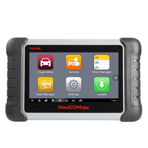
 Autel MaxiCOM MK808 auto diagnostics has Features that help gain the high praise from customers worldwide:

Read/clear codes for all available systems

Display live data in text, graph & analog for easy data review

Auto VIN technology can automatically identify the vehicle’s make, model and year information in no time

Relearn parking brake pad after replacement

Support IMMO functions

Support forced DPF regeneration and adjusting injectors

Reset Steering Angle Sensor (SAS)

Reset service mileage and service intervals

Support TPMS sensor relearn

Support battery registration and reset

autel-mk808-diagnostic-scanner-data-logging-quick-link-1


This article bases on Data Logging and Quick Link, two important operations in same level diagnostic device, sharing practical operation knowledge.


Part 1.Autel MK808 Diagnostic Scanner Data Logging:

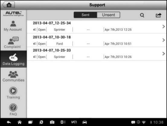
The Data Logging section keeps records of all sent or unsent (saved) data loggings on the diagnostic system. The support personnel receive and process the submitted reports through the Support platform. Support personnel will reply to the submitted issue and corresponding Data Log session within 48 hours.

autel-mk808-diagnostic-scanner-data-logging-quick-link-2


You are gonna learn how to make a reply in a Data Logging session:

  1. Tap on theSent tag to view a list of submitted data logs.
  2. Select a specific item to view the latest update of the submitted issue.
  3. Tap on the input field at the bottom of the screen and enter text. Tap the Audio button to record a voice message, or tap camera button to take a picture.
  4. Tap Send to sendyour message to the technical center.


Part 2.Autel MK808 Diagnostic Scanner Quick Link:

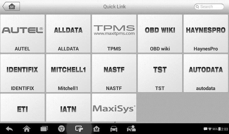
The Quick Link application provides access to Autel’s official website and to other popular automotive service websites. These sites are invaluable resources of automotive information and repair data and include forums, video training and expert consultation.

autel-mk808-diagnostic-scanner-data-logging-quick-link-3


You are gonna learn how to open a quick link:

1.Tap the Quick Link application on the MaxiCOM Job Menu. The Quick Link application screen displays.

2.Select a website thumbnail from the main section. The Chrome browser is launched and the selected website is opened.

3.Now you can start exploring the website!


That's all. Thank you for sharing your time with us!

Don't forget to contact us at:

Email:  sales@CarDiagTool.co.uk
Skype: cardiag.co.uk
Whatsapp: +86 15002705698

Or leave a message at https://www.cardiagtool.co.uk/

to tell us what suggestions or questions you have about our products.

Source:http://blog.cardiagtool.co.uk/autel-mk808-diagnostic-scanner-data-logging-and-quick-link-operation-guide/

High-quality article share: http://autelshopde.blogaholic.se/2021/sep/117519/hur-fr-jag-fjrrsupport-fr-din-autel-surfplatta/

Xhorse VVDI2 Professional Tool Tutorials: Software Update

  Xhorse VVDI2 Full version   has Highlights as follows: 1.Free Lifetime Online firmware and software update Xhorse VVDI2 Full Version V7.1....